Use Case Diagram is a graphical representation to represent the external view of a system. It shows the functional requirements of the system in terms of actors and use cases.
At first glance, it can be confused with activity diagram because both diagrams are used to show how the system responds to events. But they have their differences. The main difference between activity diagram and use case diagram is that activity diagram only shows the interaction between objects whereas use case diagram also shows the interaction between actors and objects.
The following figure shows an example of Use Case Diagram that represents all possible interactions between users, business rules and database management system (DBMS). In this diagram, each user has an actor who represents him/herself in this scenario.
Use Case Diagram For Database Management System
Use case diagram is a type of diagram that captures the relationship between the major actors and use cases of a system. The actor represents a role played by some external entity, such as a user or another system. The use case is an abstraction of a set of actions performed by one or more actors on the system.
In UML, the use case diagram has two main elements: actors and use cases. Actors are people or systems that interact with the system under analysis. Use cases are scenarios for how these actors work with the system to achieve their goals.
Use Case Diagram Tutorial
A good way to understand what use cases are is to see them in action, so let’s see how we can create a use case diagram!
Use Case Diagram is a graphical representation of use cases. A use case diagram is a comprehensive overview of the system. It shows the actors, their goals, and the system’s responses.
A UML Use Case diagram contains the following elements:
Use case name and number
Actor(s) and their associations with other actors
Actors’ goal(s)
Preferred course of actions (situations)
Extensions to the model
Use Case Diagrams are a graphical representation of the use cases in a system. They show the actors, their goals and objectives, and how they interact with each other to achieve a goal.
Use case diagrams are used as an input to a number of different analysis techniques, including:
Use case diagrams are one of the most popular requirements analysis diagrams in use today. They are easy to create, understand, and maintain by both developers and non-developers alike.
Use case diagram is a graphical representation of the functional requirements of a software system. It shows the actors that interact with the system, the scenarios in which these actors use the system and what goals are achieved by using it.
Use cases are often used in conjunction with other analysis techniques such as user interface design, object-oriented analysis and information engineering. Use cases are also used to document detailed requirements for systems under development. In this way they can be considered an evolution of structured analysis and design techniques that were developed in the 1970s and 1980s such as structured design, data flow diagrams (DFD), data modeling and entity relationship diagrams (ERD).
A use case is a description of how a particular actor uses your application to achieve some goal. The actor represents some external entity that interacts with your application — either directly or via another system.
A use case consists of:
Preconditions — conditions that must be true before an activity can begin;
Success postconditions — conditions that must be true after an activity has completed successfully;
Failure postconditions — conditions that must be true after an activity has failed;
Other non-functional requirements — constraints on when or how an activity should occur
Use Case diagrams are an important part of the software development process, as they provide a visual representation of the flow of information and data through a system.
Use Case Diagrams are used to describe the system requirements and highlight how users interact with the system. They detail what happens when certain actions occur in a system. Use Cases are often used to describe systems that are designed for users outside of IT, such as end-users or customers, but they can also be used to describe internal systems.
Use cases are typically written from the perspective of the actor who will use them (e.g., “Jim” or “Jane”). If there are multiple actors in a use case, it may be helpful to include their names in parentheses after their first appearance in each step.
Use Case Diagram Example
What is a use case diagram? A use case diagram is a visual representation of the different use cases or functionalities of an application. It is a diagram that illustrates the actors and user goals of a system, and shows how they interact with each other.
Use Case Diagrams are one of the most important documents in any project. This document is used to describe the function, behavior and flow of an application, including its requirements and design.
A use case diagram is a type of UML diagram that uses boxes with lines to represent objects in the system being described. When you create a use case diagram, you should have detailed descriptions of all the possible interactions between your system and its users, clients and other systems. These descriptions are called scenarios and they form the basis for creating use cases. Your scenario descriptions help you determine how your system will work in all situations by describing what happens when certain conditions occur during a session with the software or hardware being designed.
A use case diagram is a visual representation of the essential features of a system, and it can be used to help you identify the requirements for a given project.
Use case diagrams are also commonly referred to as use case models or use case scenarios.
All of these terms refer to the same thing: a visual representation of the ways in which people interact with a system, which is used during the software design process.
A good use case diagram will help you to understand what your users need from your software, so that you can deliver it in an effective manner.
In this tutorial we’ll go through what a use case diagram is, how it’s structured and how it should be used in practice.
Use Case Diagrams are an important part of UML. The use case diagram is used to model the functional requirements of a system.
Use Case Diagrams can be used to:
Identify use cases that need to be implemented.
Identify actors who will interact with the system.
Specify how each actor will interact with the system.
Use cases are one of the most important artifacts of a project. They form the basis for all other project documents, and they document the requirements of your system.
Use cases are also one of the most misunderstood artifacts in software development. Many people confuse use cases with user stories, and some people even think that you will never need a use case diagram.
In this post, we’ll show you how to create a use case diagram and explain why it’s so important.
Use cases are a useful way to describe the functionality of a system.
Use case diagrams are diagrams that show how use cases are grouped together. They can be used to help describe how a system is going to work, and also how it will be used.
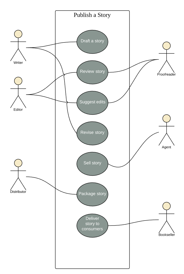
The following diagram shows an example use case diagram:
In this example, there are three use cases: Login, Add item and Show items. The Login use case has been decomposed into two more detailed use cases: Log in as admin and Log in as user. This is a common technique when you need to express complex behaviour with many steps or phases.
The diagram also shows two actors – the person using the system (User) and the administrator who can change settings (Admin).