Use Case Diagram is a must have skills for software developers. It helps in visualizing the process flow of a system and also helps in understanding different business requirements. This diagram is used to depict user interaction with the system and also helps in creating a specification for the project/application.
Use case diagram is a component of Unified Modeling Language (UML). It is used to create a visual representation of what the software or application does. A use case diagram defines the actions that can be performed by users, systems or other actors on objects within a system. An action represents an external view of what the system does to meet a particular objective.
A use case diagram consists of actors, use cases, relationships and attributes (optional). The actor represents external entities that initiate events or interactions with the system, such as users and other systems. A use case represents an abstraction of all possible ways in which something can happen in your system. A relationship represents an association between two actors or between an actor and an object (an object can be anything that supports behavior).
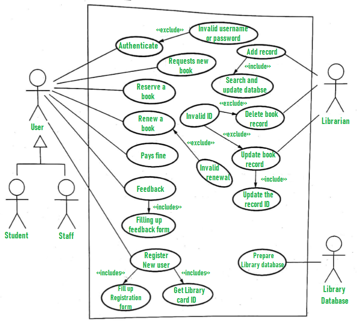
Use Case Diagram For Database
Use case diagrams are used in the software development life cycle to document the behavior of a system or subsystem. They are used to capture, analyze and visualize requirements and design them as use cases.
Use Case Diagram Template
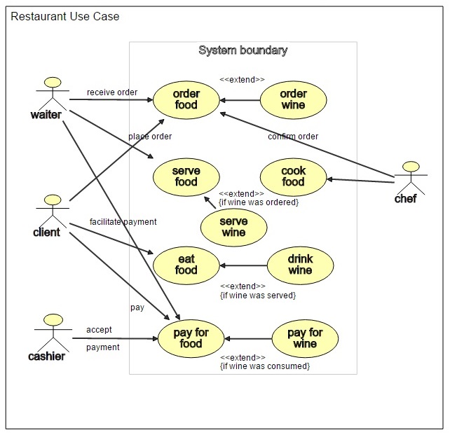
The template below can be used to create a simple use case diagram. It shows how to represent actors, primary stakeholders, secondary stakeholders and system boundaries:
Use Case Diagram Examples and Solutions
This section describes the following topics:
Include in Use Case Diagram
Actors
Primary Stakeholders
Secondary Stakeholders
Use Case Diagram Template
The use case diagram template is a simple plan that can be used to illustrate the interaction between actors and use cases. It’s graphic nature makes it easy to understand and can be used as a guide for creating more detailed documentation.
Use Case Diagram Examples and Solutions
A use case diagram is used to illustrate the relationships between actors, use cases, and other elements of a system. Use case diagrams are one of several different types of diagrams used in software development. The other types include class diagrams, sequence diagrams, collaboration diagrams, state machine diagrams, component diagrams, and activity diagrams. Use case diagrams are typically created early in the life cycle of a project when an initial understanding of the system is required. They show how individual functions interact with each other within an application or system as well as how they interact with external entities such as users or other systems (e.g., databases).
Use case diagram is a powerful and flexible tool for software requirements analysis. It is used to illustrate the functional requirements of an application.
Use case diagram is a way to describe how your system interacts with the users and other systems it interacts with. A use case diagram shows actors and their interactions with the system.
Actors can be people or other software systems such as other applications or databases. Use cases are sequence diagrams, showing the steps in a process, starting with a trigger event (usually an event from another actor).
Use case diagrams are one of the most popular ways to represent a software system, and they can be an effective way to organize information about your project.
Use case diagrams can be used to help you plan and manage a project. They can also help you to identify the actors, use cases, and other information about your application.
A use case diagram is a diagram that illustrates how actors interact with the system being developed. The diagram shows who is doing what to whom and when in relation to the system being developed. The system may be software or hardware-based, but it always includes humans as part of the system’s environment.
The basic idea behind a use case diagram is that you start with a box labeled “system boundary” at the top of your page. This represents the outside world (including people). Next you create boxes below this labeled with nouns such as actor and role that represent various roles people play in relation to your system or software. You then draw arrows between these boxes to show interactions between them.
Use Case Diagrams
A use case diagram is a visual representation of the functional requirements for an IT system. It is an important tool for communicating with all stakeholders, from business owners and users to software designers and developers.
Use case diagrams are used at various points in the software development lifecycle, including the analysis, design and implementation phases. They allow you to show how different actors (people or programs) interact with each other in a system, so that you can understand what each actor needs to do, what data they need to access and what happens when things go wrong.
There are two main types of use case diagrams:
Functional – These show how a system works from the point of view of the user. They describe how each actor interacts with other actors in order to achieve their goals (for example, by performing tasks). Each box represents an actor and arrows indicate communication between actors. A solid arrow indicates that communication is one way (for example, one actor sends data to another actor). A dotted arrow indicates that there may be more than one way for an actor to communicate with another (for example, there may be more than one way for an actor to send data).
Non-functional – These show how a system works from the point of view
Use case diagrams are a visual representation of the functionality of a software system. They are created using use case modeling techniques as part of the requirements analysis process.
Use case diagrams can be used to communicate with stakeholders and developers, and they can also be used to verify that all requirements have been captured.
In this tutorial, you will learn how to create use case diagrams using examples and solutions.
What is a Use Case Diagram?
A use case diagram is a graphical representation of the functional requirements of an application or system. It shows how actors interact with the system and explains how each use case contributes to achieving business goals.
Use cases can be used for many different purposes such as:
Communicating with stakeholders at all levels in an organization
Verifying that all functional requirements have been captured before developing software systems
Documenting software architectures
Use case diagrams are one of the most popular and widely used software design techniques. They help to structure the requirements and identify gaps in the system. In addition, they can be used to illustrate the relationships between different parts of your system.
Use case diagrams are one of the most popular and widely used software design techniques. They help to structure the requirements and identify gaps in the system. In addition, they can be used to illustrate the relationships between different parts of your system.
While working with use cases, you will also need to create other artifacts like activity diagrams, sequence diagrams, state machine diagrams and communication diagrams.
Use case diagram templates
A use case diagram template is an important part of any use case diagram definition because it provides an outline for creating a complete diagram quickly and easily without having to start from scratch each time you need a new diagram. A good use case diagram template should include all necessary elements required by your organization or industry in order to ensure consistency across all diagrams created using that template.
The use case diagram is a visual representation of the functionality provided by a system. It shows what the system can do, and the actors that can interact with it.
Use cases are a critical part of the software development process. They provide an overview of what a system does and how it will behave in response to different user actions.
A use case diagram is a diagrammatic way to document use cases, which are typically written in text form. Use cases describe how a system interacts with its users, including both functional and non-functional requirements for systems. Use case diagrams typically include actors (people or other systems), use cases, interactions between actor and use case, and preconditions and postconditions for each interaction.
A use case diagram is a graphical representation of the actors, use cases and relationships between them. It shows how actors interact with the system and one another to achieve the goal of each use case.
Use cases are an integral part of agile development. They help in identifying what needs to be developed, who is going to use it and why they will be using it.
A Use Case Diagram is a visual representation of all possible interactions between users (actors) and the system (or any other object).
The following is a basic template for creating a Use Case Diagram:
1. Actors: These are external entities that interact with your system (e.g., user) or other systems in order to accomplish some goal(s). For example, if you have a website, then users are acting as actors in this context.
2. Use Cases: A use case describes what an actor can do with your system — what functionality it provides to him/her and how he/she uses it (e.g., login).
Use case diagrams are a visual way of documenting the behavior of a system. They are not as formal as use case specifications and are used in preliminary phases of the software development process.
Use case diagrams can be in any format. Most people use boxes to represent actors, lines to represent relationships between actors and use cases, and diamonds to represent system boundaries. Use cases are often shown as stick figures or similar visual representations instead of textual descriptions.